Generate - Hot Date Kitchen

Hot Date Kitchen is an established startup in the food science and production industry that produces and sells chocolate-covered dates that are filled with sunflower butter.
HDK has recently signed a brand deal with a major New England grocery store chain, in addition to being available online and in smaller retail stores. To increase production volume, HDK consulted Generate to help automate the processes currently done by hand through a scalable, production-line prototype.
I was the Technical Lead for HDK, responsible for leading a team of 7 engineers through the technical aspect of our project. From this role, I gained engineering management experience and improved my engineering skills related to electromechanical projects.


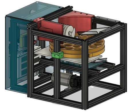
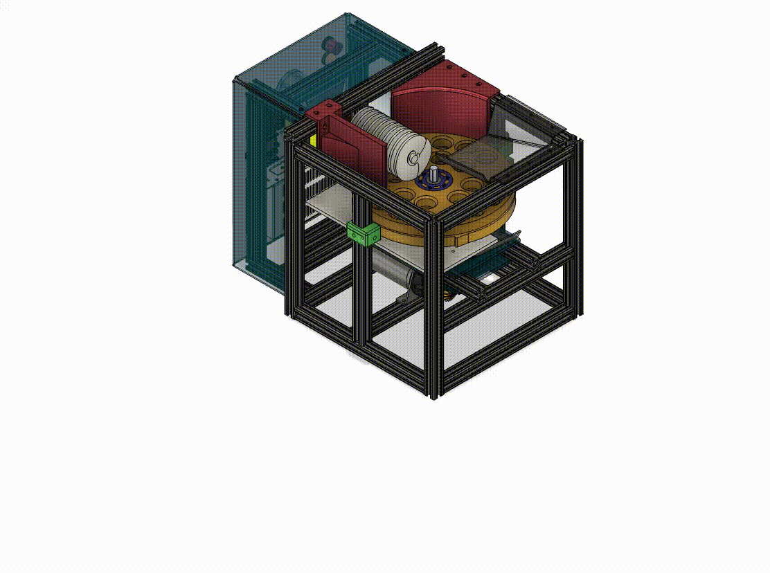
Final Showcase Assembly
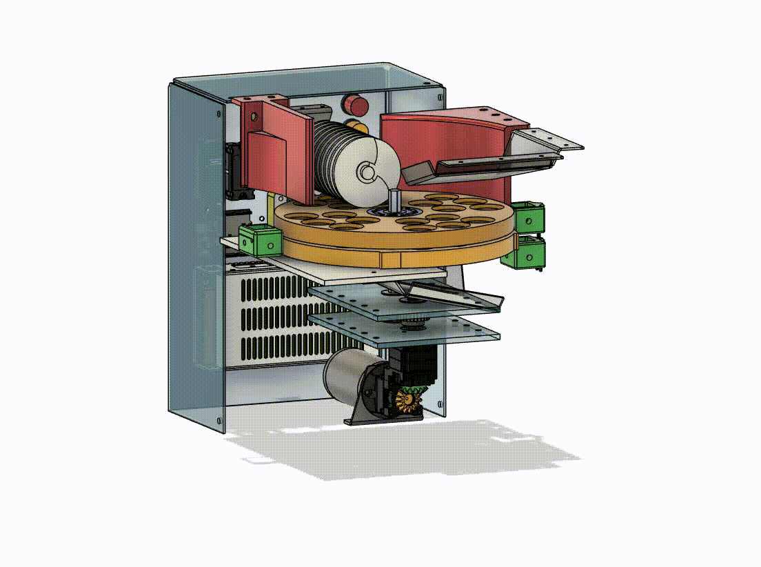
Final CAD Assembly
Brainstorming Process
Problem: Design the overall system and key mechanisms for a machine that will cut dates as efficiently as possible, while accounting for scalability and modularity for future iterations.
Action:
-
As Technical Lead, led a several-day brainstorming process with all engineers.
-
Used brainstorming methods learned from an Iterative Product Prototyping class
-
First day focused on market research and learning from existing alternatives
-
Second day focused on identifying constraints and overall functionality
-
Final day focused on designing mechanisms to accomplish overall functionality

Linear Belt Idea

Final Rotary Plate Idea
Result:
-
Team decided on a rotary cutting system
-
Dates would be sorted into rotating plates. The rotating plates would spin dates across a stationary wire with enough tension to withstand cutting several dates simultaneously. The rotating plates would spin cut dates over an exit slide where the dates would fall into a crate.
-
Rotary system was chosen over linear belt system due to manufacturability (CNC milling plates vs designing custom belt system to hold dates), smaller footprint, and cost.
-
Stationary wire was chosen over stationary blade or rotary blade due to ease of cleaning, replacement, and safety concerns.
-
Brush roll assembly would push unsorted dates backwards to ensure all dates would fall into rotary plate slots
Subsystem: Rotary Drive Train
Problem: Design a rotary drive train with enough torque to cut dates, and enough speed to reach output of 12 dates per minute. System must be robustly mounted, minimize space taken up in assembly, and interface with rotary plates that will hold dates.
Action:
-
Employed DOE to gather data on the torque required to cut dates
-
Designed rig that would cut dates imitating a 9” radius wheel
-
Force probe measured required tensile force to pull and cute dates across a stationary wire
-
-
Used data set to determine motor torque and RPM specs and required gear ratio
-
Selected high torque DC motor for high torque drive train application. Based on continuous rated torque calculations, 27.8:1 gear ratio was necessary. Selected 28:1 gearbox with external 2:1 spur gear ratio (56:1 overall) to achieve necessary torque while maintaining sufficient RPM.
-
Designed robust motor mounting system with right angle gear box to save vertical space in assembly and to prevent motor wobbling and loosening from continuous vibrations.
-
Designed shaft mounts with tolerance analysis performed to design proper bearing press-fit housing and gear interfacing on 3D printed part

Result:
-
Drive train outputted necessary torque and RPM to cut several dates simultaneously, and to operate for long periods without stalling.
-
Drive motor did not wobble or loosen after 2 hours of operation.
-
Bearings were press-fit into mount without wobbling or loosening after 2 hours of operation, shafts were mounted with tight vertical alignment, and gears properly interfaced allowing for efficient torque transfer between input and output shaft
-
Drive train powered final prototype to cut 30 dates per minute – 2.5x the amount requested by the client


Labeled Rotary Drive Train
28:1 Gearbox
CIM Motor
2:1 Spur Gears
Motor Mount
Right Angle Gearbox

Minimum Gear Ratio Calculations Using Date Cutting Data
Subsystem: Assembly Frame & Guiding Features

Main Body Frame


Wire Mount Frame

Electronics Box Frame
Drive Train Frame
Problem: Create a robust frame that will support all components, minimize footprint, and help guide/sort dates if necessary.
Action:
-
Selected aluminum 80/20 as frame body due to its modularity, rigidity, and existing CAD and component library
-
Created block CAD to locate components to maximize use of space within assembly. OTS mounts selected for motors, custom mounts designed and 3D printed in PLA for specific components with complex geometry
-
Designed for easy access to electronics box, accommodated for additional electronics weight by utilizing wide, rectangular base, and mounting heavy components toward bottom of assembly
-
Designed and 3D printed additional guiding features as necessary – “Date Shell Rail” to prevent dates from rolling out of machine, “Date Backboard” to ensure unsorted dates are pushed back into slots
Result:
-
Modularity of frame allowed for easy modification and replacement of components
-
Wire mounting subsystem had four iterations over the course of the semester – each could be easily switched out for a new iteration within minutes
-
-
Guiding features prevented dates from falling out of machine and ensured each date was cut
-
Final assembly had no issues with wobbling after 2+ hours of continuous operation
-
Final assembly allowed user to easily access electronics box while minimizing interference with internal components


Block CAD to locate components
Date Backboard
Shell Rail Back
Shell Rail Side
Subsystem: Full 1:1 CAD Model
Problem: Full 1:1 CAD model in Fusion360 required to use as reference for final prototype assembly, to hand off to clients, and to display at product showcase. Linkages should be fully operational to show system functionality.
Action:
-
Compiled CAD for all OTS parts
-
Tolerance analysis performed based on CAD assembly to spec fabricated part dimensions for final prototype assembly
-
Assembled drive train with working joints and motion links
-
1:1 motion link chosen over 56:1 assembly gear ratio to show viewers direct relation between motor shaft rotation and rotary plate rotation
-
-
Created animation files to display in final presentation
Result:
-
Fully functioning 1:1 CAD model for product showcase with moving linkages, including gearbox internal planetary gears
-
Revolved and explode animations to show functionality and assembly of prototype
-
Explode animation delegated to junior engineer
-
-
Final assembly of 100+ functioning joints and 72 unique components
-
Industry-standard engineering drawing and labeled diagram of entire assembly handed off to clients
Final CAD Rotate Animation


Dimensioned Engineering Drawing
Labeled Front
Labeled Back
Miscellaneous Contributions
-
Managed team of four mechanical engineers and two electrical engineers, overseeing design of each subsystem, including wire mounting, brush roll, entry and exit slides, circuit design, and circuit box system.
-
Helped design shaft coupler from motor to brush roll
-
Proposed set screw design used in final prototype
-
-
Helped design entry and exit slide using sheet metal tool in Fusion360
-
Helped compile dataset of 60+ sample of dates to inform part dimension and design choices
-
Helped design rotary plates to be made of CNC milled Delrin due to food safety, cost, and weight
Final CAD Explode Animation

Exit Slide of Acrylic Sheet
Include Brush Roll photo here,
uploaded soon


Product Final Showcase
Video of Final Working Product